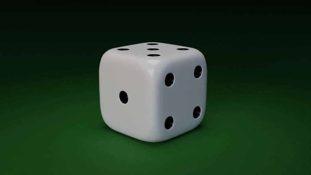
In which I document the steps I took to go from the default cube to a dice in Blender.
No, really. That’s it.
It’s not much – well, there’s a lot of steps – but it’s honest work.
Last week’s post about Plasticity and the revival of NURBS has had me thinking about writing a few more posts dedicated to 3D modelling, and since Blender 4.01‘s release a earlier this week, it seemed as good a time as any to do a modelling writeup.
I’m going describe my process for modeling a die with softened edges, following some of Ian McGlasham’s advice shared on his YouTube channel and website:
I don’t want this to be a tutorial, but at the same time I can’t help but feel that this will turn out like a tutorial. I do think, however, that it’s important to show I’ve thought about his techniques, because the more solutions to modeling problems that exist for other people to find, the better. In particular, I’d like to show some uses of the F2 and LoopTools addons I mentioned in my last post, as these are pre-installed with every Blender version and have a lot to offer. The information about what these addons do is sparse on YouTube. The official LoopTools website shows what each of its functions can do, but in my experience, scratching my head as to why they were useful left me with more questions than answers:
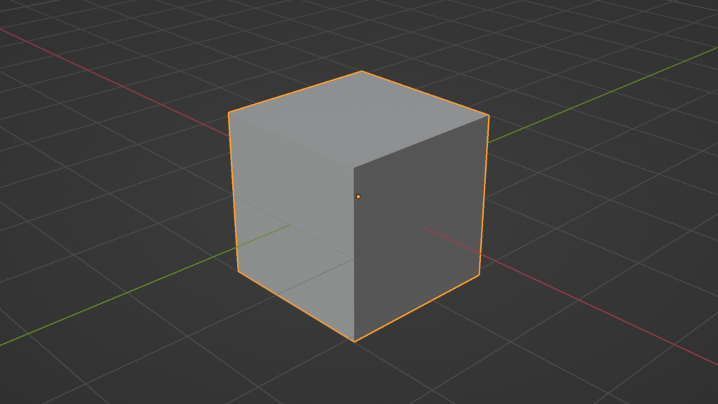
Shapewise, simple objects like the dice are pretty easy to define. You’ll typically use one of Blender’s primitives and work your way from there. Take a guess as to which primitive is best for modeling a dice…
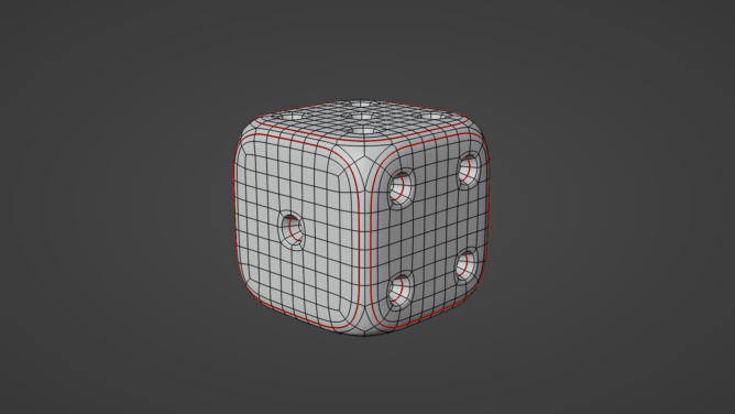
Despite its polygonal appearance, loops are the most important structural unit in SubD modeling – faces and vertices are important, of course, but loops define the structure of the model – where curvature begins, and where we control that curvature:
Part of the reason there’s an emphasis on making SubD models solely with quads is because it makes loops easier to select and edit. Also, deformations – Simple Deform, Lattice, Shrinkwrap, etc. – as well as smooth shading algorithms play nice with quad topology, for some mathematical reason that I’m not knowledgeable enough to tell you.
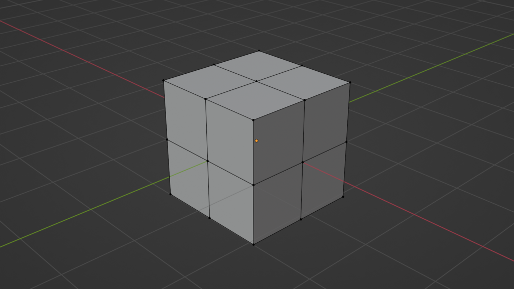
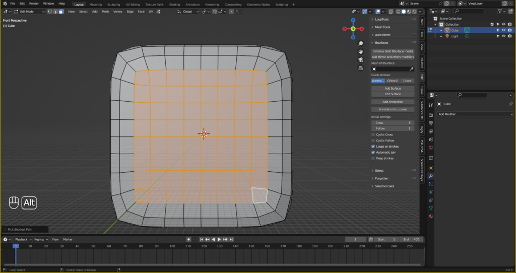
I pressed TAB to go into Edit mode, then pressed A to select all the vertices, and then right-clicked (or press CTRL+E) to bring up the edge menu and chose ‘Subdivide.’ This added two full loops running through the top, bottom and cross section of the cube, and another full loop running through the cross section.
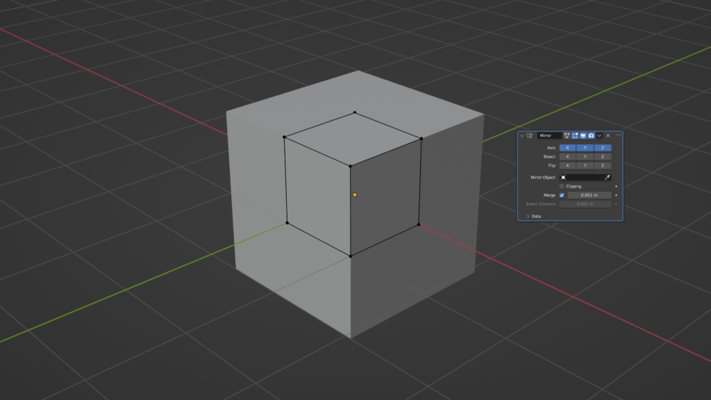
I only needed one of these quadrants, because I can symmetrize the base shape with the Mirror modifier. I selected one of the vertices in the corners connected to three edges, pressed CTRL and + to expand the selection, CTRL and I to invert it, and then pressed X and chose Delete Vertices:
Then I added the Mirror modifier, and set it to mirror the model on all axes.
At this point, I needed to inset each face to establish where the boundary between the sides of the die and the curvature connecting those sides. I pressed 3 to go into Face select, selected one face, pressed I to inset, and typed 0.3. Because the Mirror modifier is in effect, I toggled the inset operation’s boundary setting off.
The section I’ve just inset needs 3 extra full loops like in the first step. On each side of my model, I pressed CTRL and R to add one loop, left clicked to confirm it, but before left clicking again to confirm its placement, I pressed E to make it so the new loop matched the directional flow of one of the edges. This was indicated by the red dot that appeared on the opposite edge. I wanted the loops to run straight, so I pressed F to flip the red dot onto the straight edge:
Slight tangent: In the process of doing this, I learned one of the many things that Blender doesn’t tell you. Here’s the manual for the Edge Slide tool I just used2:
Now, I could be reading this wrong, but I can’t find any paragraph pointing out that the position of your mouse in the 3D viewport decides the loop you’re trying to match!
I applied the Mirror modifier by pressing CTRL and A, and then applied a Subdivision Surface modifier.
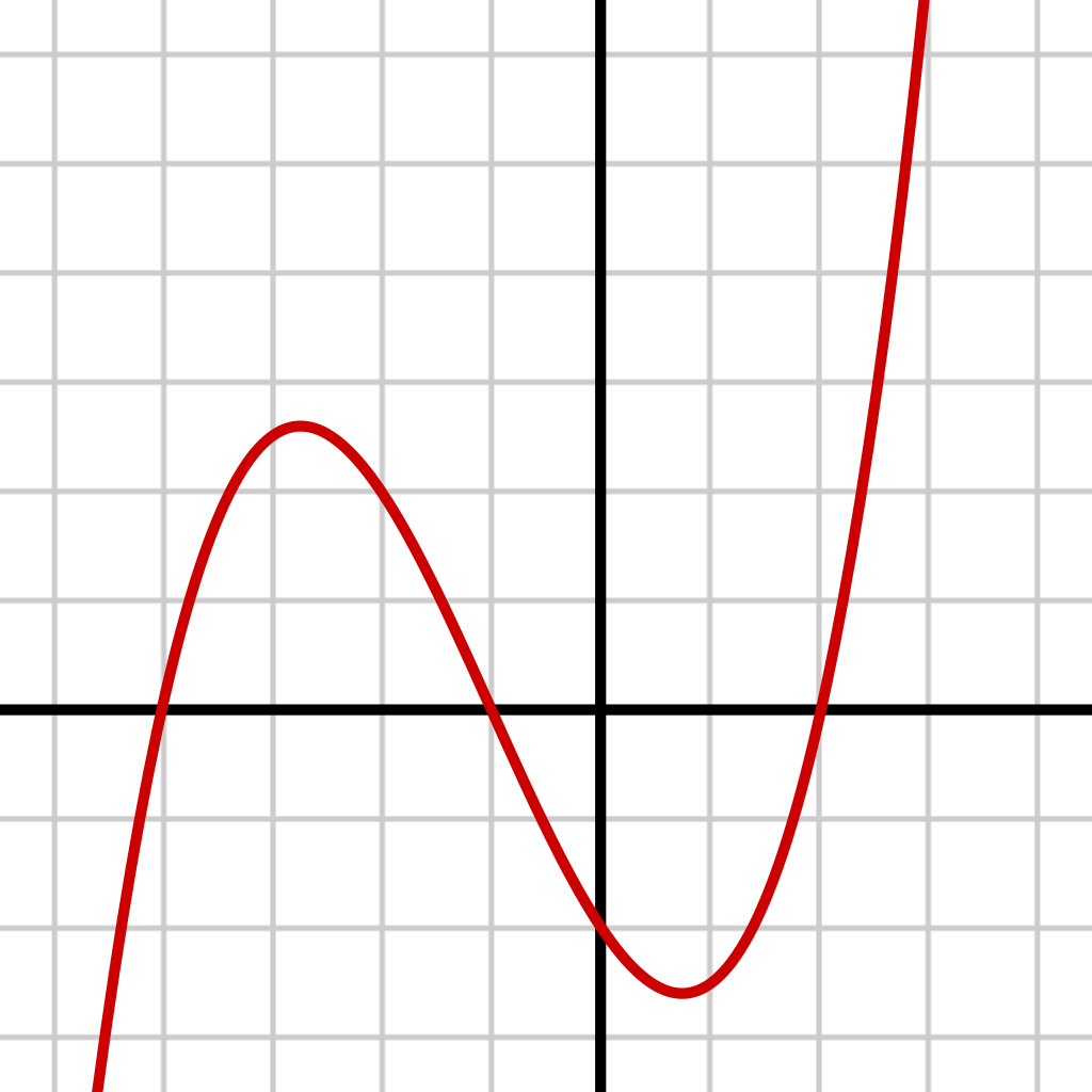
Time for an interesting tangent: The Subdivision Surface modifier can be used to refine the limit surface, but when applied destructively, it will refine the control cage that I’m currently building. It leaves me with four times as many vertices, which have been smoothed and averaged using bicubic interpolation. It’s like linear interpolation, but a bit more complicated. In linear interpolation, you draw a straight line between two points on a graph, and then use those points to estimate the positions of other points. In cubic interpolation, instead of a straight line, it’s a cubic polynomial curve…
…One of these things. It follows that bicubic interpolation is the same as cubic interpolation, but done across two dimensions.3
The model still wasn’t ready. The impact of distributing these new vertices bicubicly is that the local geometries where I was going to inset aren’t totally straight. They’ve been pulled like a weight on a sheet of rubber, but in reverse:
It’s an easy fix, and I can save myself time by preparing the model for symmetrisation with the Mirror modifier again. I pressed Numpad 1 and Numpad 5 to view the model from a front orthographic perspective, TABed into Edit mode, pressed 3 to go into Face select, and SHIFT and Z to view the die’s wireframe. I then drew a marquee around all the quads that are in the -Z axis. Holding SHIFT, I drew another marquee around all the quads in the -X axis. Finally, I pressed Numpad 3 to change my viewing angle to Right Orthographic, and, holding down SHIFT again, draw a third marquee around all the quads in the -Y axis. I pressed X, chose Delete Faces, and added a Mirror modifier set to mirror on all axes again:
Straightening these loops out was an intricate task, but one that allows me to show how the usefulness of Blender’s transform pivot point, as well as a little bit of what LoopTools can do. Pressing 1 in Edit mode to switch to Vertex Select, I hovered my mouse over one of the boundary vertices whose edge loop borders the six-span vertex, and held down ALT while I left clicked.
It’s important this vertex is coloured white, because when I set the transform pivot point to Active Element, if I then scale this loop along an axis by pressing S, and then X, Y, or Z, Active Element will consider the co-ordinates of this vertex as the origin point:
While scaling this loop in the Y axis, I typed 0, so that all of the vertices running along this loop would be positioned with the exact same Y position as the active element!
I could interpolate this scaling automatically by ALT clicking the boundary edge, and selecting the Curve function in LoopTools. Checking the Boundaries box assures that only the unselected loops in-between the selected ones would be affected:
If I didn’t do that, the Curve tool would consider all of my unselected vertices, which will produce pretty weird results:
I repeated these steps along the other two sides of the die, scaling along their respective axes:
I still needed to straighten the grid inside my terminating loops. To do this, with the Active Element transform pivot point, I positioned my mouse along one of the edges of the vertex with 3 poles running out of it, and ALT clicked. Like in the previous steps, I scaled them along their respective axes, setting the scaling to 0. After scaling all the loops, I highlighted each of them again, and used another LoopTools function, Space, to distribute the vertices along these loops perfectly:
Those quads don’t look straight, but the vertices making up the terminating loop are. I can delete them, and use the F2 addon to fill this grid back in. In Face select mode, I selected one of the quads inside the terminating loop, held down SHIFT and CTRL, and selected the quad on the opposite side:
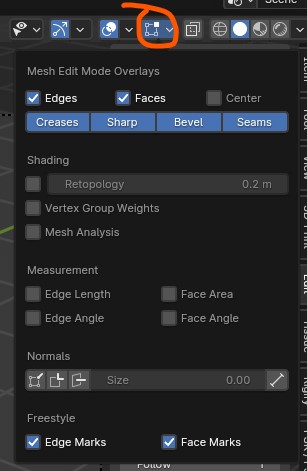
Going back into Vertex Select, with the F2 addon enabled, I selected a corner vertex, and pressed F to fill it in with a quad. I did this for every square in the grid, and then, in the Viewport Overlays dropdown menu4, I enabled Face Area and Edge Angle to check that they were all identical:
The last thing I needed to work on was the corner of the die. Any vertex that has three, five or more than five connected edges experience a greater intensity of ‘pull,’ as described here:
If I add a SubD modifier, turn Smooth Shading on, and use a glossy MatCap, you may see the specular reflection flow into the corners of the die, and then get stuck:
Honestly, in most cases, I feel like someone’s not going to notice, but fixing this area is another great opportunity to use the F2 addon.
I selected the vertex, and deleted it, leaving a hole. For each of the remaining vertices with edges at concave angles, I selected it, pressed F to fill in a quad using F2, and right-clicked to leave it in place:
This left me with some isosceles and equilateral-shaped gaps. I didn’t need the equilateral-shaped gaps, so I got rid of them by selecting the vertices, then pressing M and choosing Merge At Center:
With the remaining vertices, I ALT clicked the loop, pressed F to fill it with an N-gon, switched to Face Select mode, right-clicked and selected Poke Faces. The pole it made in the centre was indented slightly, so I changed the Offset value in the dialogue box to 0.6.5 I could then get rid of the 6-span pole by selecting the longer edges and pressing X > Dissolve Edges.
Turning the matcap on again, the light still gets pulled towards the pole, but the overall effect is significantly reduced.
With the Mirror modifier applied, it was time to make the pips. For an accurate die, all opposite pairs of faces must add up to 7 (1 is opposite 6, 2 is opposite 5, and so on). I selected the vertex that I wanted to be the centre of the pip, and pressed CTRL and + to expand the selection. Then, I used the circle tool from LoopTools, with the Influence slider set to 50%. This established a gradual transition from the local geometry to the boundary, which I then made by pressing I to inset , typing 0.2, and using Circle again, this time with Influence set to 100%. The toggling of the Offset Relative setting was necessary as to keep the inset size relative to the outer loop. I inset the loop a further three times, once with 0.2 thickness, and then twice with 0.5 thickness.
When making the six side, due to how Blender selects faces, I had to do the outer two rows of pips first.
Pips done. Insetting faces within a local geometry establishes a new boundary, and thus, another area of local geometry. The first inset is intended as a holding loop, to contain the curvature defined by the second loop, which is a control loop:
For my final trick, I’ll indent these pips equally, all at the same time. Selecting the center vertex in one of the pips and expanding the select with CTRL and +, I swapped to face select mode, then pressed SHIFT + G and chose Perimeter, and then reduced the select with CTRL and -:
With all sides selected, I set the transform orientation to Normal and the transform pivot point to Individual Origins. As I said in my last post, what a ‘normal’ is in Blender can sometimes be confusing; think of normals as imaginary lines running perpendicular to the model’s polygons. Scaling or moving vertices in the Z axis with this these transform settings will always move them directly along their normal. Normal orientation and individual origins pivoting almost always go with each other.
Proportional editing was then enabled with O to make the indents through spherical faloff. I reduced the influence of the falloff with my mouse wheel so that only the three inner inset loops were affected:
And with that, the die is finished! What I’ve just made is the framework mesh, and if I’ve done it properly, I can go on to use it for any future projects that may need a dice of this design. For example, if I ever make a game, the framework mesh could be used to produce however many LOD models I need through reducing its resolution.6
That felt like a nightmare to write out.
Sure, documenting how you make a model can be really useful, but trying to write that down in prose WITHOUT sounding repetitive is like threading a needle. 3D modelling’s always been an area of learning for me where a visual aid is absolutely required. The Blender experience is one of hidden hotkeys and navigating text menus, and translating that can be quite jarring: “I did this, and then this, and HERE is a clip of me doing this kthxbye.” With video, there’s no such gap between action and explanation – you see the artist make decisions and explain them there and then.
YouTube’s been around long enough that it feels like it’s always been there. You wanna know how folks upskilled back in the day?
Not that it’s an impossible task – Polycount has had a sticky thread for asking how to model things for over fifteen years, and it’s seen countless users pass through and offer advice:
Subdivision surface modeling with these techniques is a real brain teaser, and I like that. It’s been very rewarding to theorycraft different ways of making designs and testing those ideas in Blender. If I ever do a thing like this again, though, it’ll probably be a video.
It sounds so futuristic. Blender was in 2.x for longer than I’d been alive by the time 3.0 dropped. Blender 4.0 sounds like it’s the year 2015 in Back to the Future Part II, or any Mega Man game taking place in the year 200X. ↩︎
Loops can be positioned like this after the fact by pressing GG and then E. It’s the exact same tool. ↩︎
If SubD modeling’s taught me anything: when teenage you asks, “will I ever use this?”, adult you will go on to thump their desk and belt an affirmative yes. You won’t know when, you won’t know where, but I guarantee you that high school maths problems will creep up on you when you least expect them. Because, as is my favourite Pratchett adage: million-to-one chances crop up nine times out of ten. I’d probably have loved this visual maths when I was 13. ↩︎
In Blender 4.0, these options have been separated into the Mesh Edit Mode Overlays dropdown. I had to do this in 3.6.5 because I couldn’t get Screencast Keys to work, even after I reinstalled it. ↩︎
A more accurate way would probably be to add the pole to its own vertex group, and let either the Smooth Laplacian or Smooth Corrective automate it ↩︎
LOD means ‘Level of Detail.’ Games have to run in real time, so one way to keep things efficient is to replace a fully-detailed model with a lower-resolution one when an object is at a certain distance from the camera. ↩︎